A reliable compressed air dryer system is more than a dryer installed downstream of an air compressor. The performance of the entire treatment system depends on how the receiver, moisture separator, filters, dryer, storage tank, drains, piping, and point-of-use equipment are arranged.
A practical industrial configuration is:
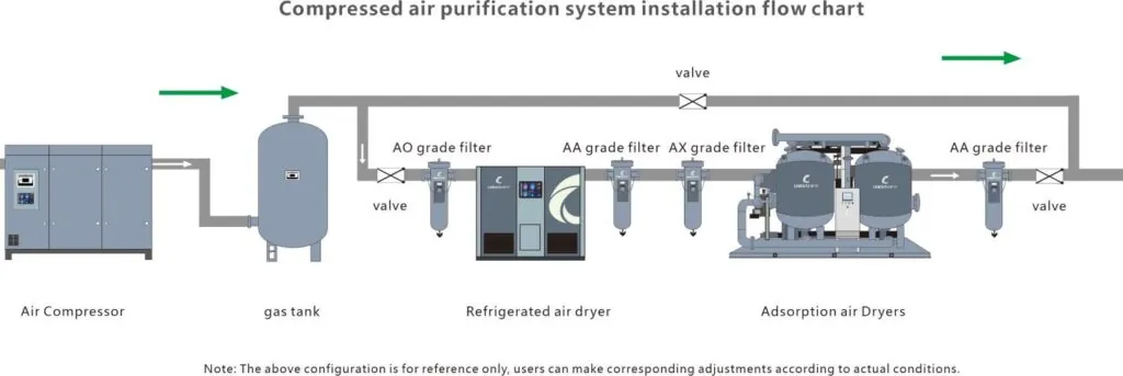
Air compressor → aftercooler/moisture separator → wet receiver → pre-filter → air dryer → after-filter → dry air receiver → distribution piping → point of use.
This arrangement helps reduce moisture loading, protect the dryer, stabilize airflow, control contamination, and deliver compressed air at the required pressure dew point and cleanliness.
Why Compressed Air Dryer System Layout Matters
Atmospheric air naturally contains water vapor. Compression concentrates that moisture, and the compressed air also leaves the compressor at an elevated temperature.
As the air passes through an aftercooler, receiver, piping, and other downstream equipment, it cools. Part of the water vapor then condenses into liquid.
If moisture is not adequately controlled, it can contribute to corrosion, pneumatic equipment problems, process contamination, coating defects, freezing in cold environments, and additional maintenance.
A properly designed air-treatment system addresses several different tasks:
| Component | Primary Function |
|---|---|
| Compressor | Produces compressed air |
| Aftercooler | Reduces compressed-air temperature |
| Moisture separator | Removes bulk liquid condensate |
| Wet receiver | Buffers demand and allows additional condensate separation |
| Pre-filter | Protects downstream treatment equipment |
| Dryer | Reduces water vapor and controls pressure dew point |
| After-filter | Controls downstream particles or other contaminants |
| Dry receiver | Stores treated compressed air and supports short demand peaks |
| Distribution system | Delivers treated air to end users |
| Point-of-use treatment | Provides additional treatment or regulation where required |
The dryer is therefore one part of the overall air-treatment system rather than a stand-alone solution for every contaminant.
Recommended Compressed Air Dryer System Layout
A common industrial arrangement is:
Compressor → aftercooler → moisture separator → wet receiver → pre-filter → dryer → after-filter → dry receiver → distribution → point of use
The exact configuration can vary according to compressor type, dryer technology, air-quality requirements, operating profile, and available space.
For a broader range of industrial treatment equipment, the Lingyu compressed air treatment product range includes refrigerated dryers, adsorption dryers, combined systems, filtration, and related equipment.
1. Air Compressor
The compressor generates compressed air but does not by itself provide the final air quality required by most industrial processes.
Compressed air leaving the compressor can contain:
- Water vapor
- Condensed water
- Solid particles
- Oil aerosols, depending on compressor type
- Oil vapor
- Wear debris
- Other system contaminants
The downstream treatment system must be designed around the required final air quality.
2. Aftercooler and Moisture Separator
Compressed air leaving the compressor is typically hot.
An aftercooler reduces its temperature, which causes part of the water vapor to condense. A downstream moisture separator then removes much of this bulk liquid water.
This stage can significantly reduce the moisture load on the air dryer.
Sending unnecessarily hot air or large quantities of liquid condensate directly into the dryer can reduce drying performance and increase treatment load.
The condensate separator should therefore have a reliable drainage system.
3. Wet Receiver Before the Dryer
A receiver located upstream of the dryer is often called a wet receiver.
A typical sequence is:
compressor → aftercooler/separator → wet receiver → pre-filter → dryer
The wet receiver performs several useful functions.
Additional Condensate Separation
As compressed air continues to cool in the receiver, more water can condense.
Removing this liquid before it reaches the dryer reduces the moisture load on downstream treatment equipment.
Airflow Buffering
The receiver stores compressed air and can help smooth short-duration changes in demand.
This can reduce sudden airflow peaks passing through the dryer.
Compressor Control Support
Depending on the compressor and its control strategy, properly sized receiver capacity can help reduce excessive loading and unloading cycles.
Receiver volume should therefore be considered as part of the compressor control system rather than selected independently.
Condensate Drainage
A wet receiver must have an effective condensate drain.
A failed or blocked drain allows water to accumulate and can eventually send liquid downstream.
4. Pre-Filter Before the Dryer
A pre-filter protects the dryer from contaminants that could reduce performance or shorten equipment life.
The basic arrangement is:
wet receiver → pre-filter → dryer
Depending on the compressor and required downstream air quality, upstream treatment may include a water separator, particulate filter, coalescing filter, or higher-efficiency oil-removal stage.
Lingyu’s precision compressed air filter range includes several filtration grades for different particle and residual-oil requirements.
For example:
| Filter Grade | Particle Rating | Residual Oil |
|---|---|---|
| AO | ≤1.0 μm | ≤3 ppm |
| AA | ≤0.1 μm | ≤0.1 ppm |
| AX | ≤0.01 μm | ≤0.05 ppm |
| ACS | Not specified as a particle grade | ≤0.003 ppm |
The correct combination depends on compressor type, dryer technology, and the final air-quality requirement.
Pre-Filtration for Refrigerated Dryers
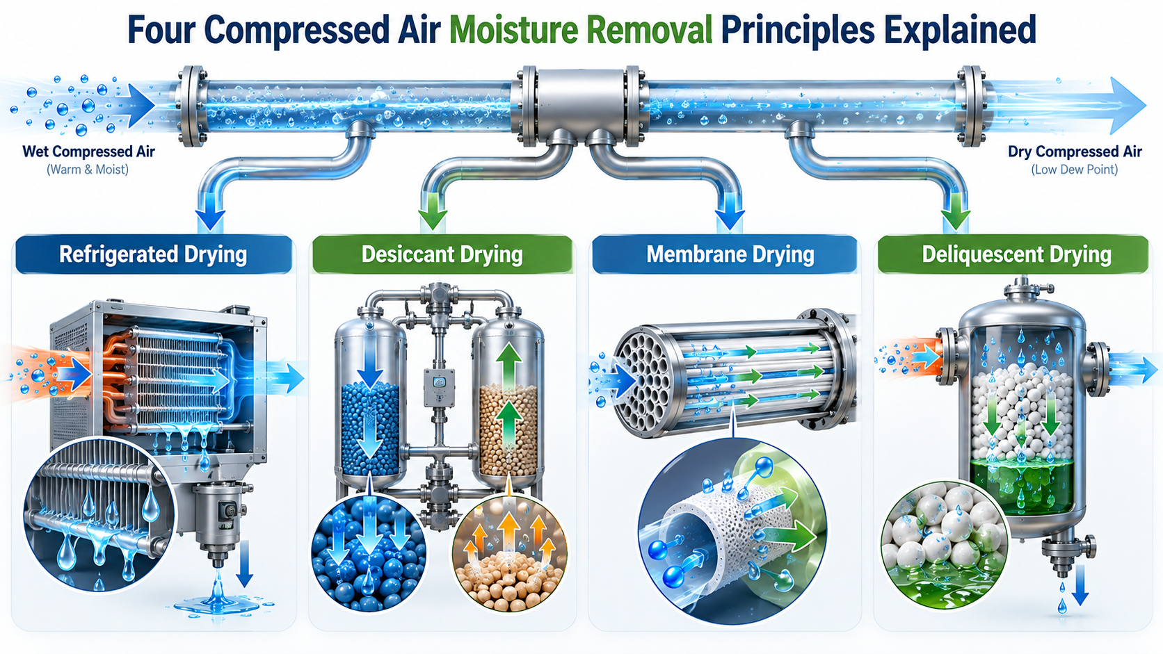
A refrigerated dryer removes moisture through cooling and condensation.
Good upstream filtration helps reduce contamination of the dryer’s heat exchangers, separator, drains, and internal passages.
However, filtration should not be confused with drying.
A filter can remove liquid droplets or aerosols according to its design, but it does not replace the dryer when water vapor must be reduced to a specified pressure dew point.
Pre-Filtration for Adsorption Dryers
Pre-filtration becomes especially important with adsorption drying.
Oil and bulk liquid contamination can damage the desiccant, reduce adsorption efficiency, and shorten its usable life.
A desiccant air dryer should therefore be installed with upstream treatment appropriate for its desiccant and inlet-air specification.
5. Refrigerated Air Dryer
For many general industrial compressed air systems, refrigerated drying provides sufficient moisture control.
A refrigerated compressed air dryer cools the compressed air until water vapor condenses. The liquid is then separated and automatically discharged.
For Lingyu’s conventional AH air-cooled and WH water-cooled refrigerated dryer technology, typical operating specifications include:
| Parameter | Specification |
|---|---|
| Rated inlet pressure | 0.7 MPa |
| Operating range | 0.6–1.0 MPa |
| Rated inlet temperature | 50°C |
| Maximum inlet temperature | ≤80°C |
| Pressure dew point | 2–10°C |
| Rated ambient temperature | 32°C |
| Ambient range | 2–45°C |
| Pressure drop | ≤0.025 MPa |
A 2–10°C PDP can suit many indoor industrial applications where downstream temperatures remain above the delivered pressure dew point.
6. Adsorption Dryer for Lower Dew Points
Where substantially lower pressure dew points are required, adsorption technology is normally considered.
For example, Lingyu’s CH Series heatless regeneration adsorption dryer specifies a PDP of −50°C to −20°C under its designated operating conditions.
Adsorption drying is particularly relevant where compressed air is exposed to freezing temperatures or where a moisture-sensitive process requires deeper drying than conventional refrigeration can provide.
The required PDP should therefore determine dryer technology before the system is sized.
7. After-Filter After the Dryer
An after-filter is installed downstream of the dryer where the final air-quality requirement calls for additional particle or contaminant control.
A typical arrangement is:
dryer → after-filter → dry receiver
For adsorption systems, an after-filter is particularly useful for controlling desiccant dust that may migrate downstream.
This helps protect pneumatic valves, cylinders, instrumentation, process equipment, and final production systems.
The exact filtration grade should be selected according to the specified final air quality rather than applying the same filter combination to every plant.
8. Dry Air Receiver After the Dryer
A second receiver can be installed downstream of the dryer and filters.
This is commonly referred to as a dry receiver.
Its main functions include storing already-treated compressed air, supporting short periods of high downstream demand, reducing pressure fluctuations, and helping stabilize delivery to the production network.
The arrangement becomes:
dryer → after-filter → dry receiver → distribution
Because the receiver contains treated air, it can provide a temporary reserve without immediately increasing flow through the dryer.
Should the Receiver Be Before or After the Dryer?
Both positions can be useful because the two receivers perform different roles.
Wet Receiver Before the Dryer
Primary benefits include bulk condensate separation, airflow buffering, and reducing sudden dryer loading.
Dry Receiver After the Dryer
Primary benefits include storing treated air, supporting short-duration demand peaks, and stabilizing downstream pressure.
Large industrial installations may therefore use both.
The correct arrangement depends on demand profile, compressor controls, dryer technology, required storage capacity, and available space.
Receiver Sizing Should Match the System
There is no single receiver volume that is correct for every compressed air station.
Receiver sizing should consider compressor capacity, control method, allowable pressure variation, demand fluctuations, and required storage duration.
A receiver should not be added simply with the assumption that more storage automatically reduces energy consumption.
Its energy impact depends on how the compressor control system responds to the additional storage volume.
Dryer Sizing in the Complete System
One of the most common design errors is selecting a dryer only from the compressor’s nominal CFM or m³/min rating.
Actual dryer capacity depends on operating conditions.
Maximum Airflow
The dryer must handle the maximum realistic airflow passing through it.
If several compressors can operate simultaneously into a common header, their combined flow may need to be considered.
Inlet Temperature
Higher compressed-air temperature increases both thermal and moisture load.
An effective aftercooler and upstream condensate separator can therefore improve dryer operating conditions.
Operating Pressure
Dryer capacity changes with system pressure.
Use the actual expected operating range rather than assuming that nameplate capacity remains unchanged at every pressure.
Ambient Temperature
Ambient temperature is especially important for air-cooled refrigerated dryers.
High surrounding temperature makes condenser heat rejection more difficult and can reduce effective dryer capacity.
Cooling-Water Conditions
For water-cooled dryers, cooling-water temperature and pressure are important.
Lingyu’s conventional WH Series specifies a cooling-water pressure of 0.2–0.4 MPa, rated water temperature of ≤32°C, and operating water-temperature range of 2–38°C.
Required Pressure Dew Point
PDP determines which dryer technology is suitable.
Do not select a refrigerated dryer when the downstream environment requires a PDP below what that technology can reliably provide.
Use Correction Factors Instead of Arbitrary Oversizing
Nominal dryer capacity is based on specified rated conditions.
When actual inlet temperature, pressure, ambient temperature, or other conditions differ from the rating basis, manufacturer correction factors should be applied.
The goal is not simply to install a dryer 10%, 20%, or 30% larger.
The better approach is:
actual peak flow ÷ applicable correction factors = required rated dryer capacity
The exact calculation method should follow the selected manufacturer’s technical data.
Pressure Drop Across the Complete Treatment System
Compressed air system efficiency is affected by the cumulative pressure drop through:
separator + filters + dryer + valves + piping + fittings + point-of-use equipment
Each individual component may have a relatively small pressure drop, but the total can become significant.
If excessive pressure loss forces the compressor to operate at a higher discharge pressure to maintain adequate point-of-use pressure, compressor energy consumption can increase.
Pressure drop should therefore be treated as a system-level design parameter.
Reducing Pressure Drop
Several design practices can help control pressure loss.
Select filters and dryers with adequate flow capacity, use correctly sized piping, minimize unnecessary restrictions, maintain clean heat exchangers and filters, monitor differential pressure, and avoid continuously operating treatment equipment above its corrected flow capacity.
For applications where low dryer pressure drop is especially important, Lingyu’s 3-in-1 plate heat exchange refrigerated dryer specifies pressure drop below 0.015 MPa.
The PD design integrates the evaporator, air-to-air exchanger, and water separator in an aluminum plate heat exchanger.
Correct Bypass Arrangement
A maintenance bypass can allow a dryer to be isolated without shutting down the entire compressed air station.
A simplified arrangement can include isolation valves at the dryer inlet and outlet plus a bypass line around the treatment equipment.
During normal operation, the bypass valve should remain closed.
If the bypass is accidentally left open, untreated wet air can mix with or completely bypass dried air, raising downstream pressure dew point.
Bypass piping should also be adequately sized so it does not create excessive restrictions when intentionally used.
Condensate Drain Placement
Reliable drainage is essential throughout the wet side of the compressed air system.
Potential condensate collection points include the aftercooler separator, wet receiver, pre-filters, refrigerated dryer, and other low points where liquid can collect.
Drain failure can occur in two important ways.
A failed-closed drain allows condensate to accumulate.
A failed-open drain continuously wastes compressed air.
Drain condition should therefore be included in normal system inspection.
Air-Cooled Dryer Installation
An air-cooled refrigerated dryer system requires sufficient ventilation around the condenser.
Lingyu’s conventional AH Series is intended for indoor installation on a level concrete floor, with a minimum clearance of approximately 1.5 m.
Avoid locations where the dryer can draw in hot compressor exhaust air or where ventilation openings are obstructed.
Dust accumulation on an air-cooled condenser can also reduce heat transfer and should be addressed according to actual site conditions.
Water-Cooled Dryer Installation
A water-cooled refrigerated dryer system should be evaluated as part of the facility’s cooling-water infrastructure.
In addition to pressure and temperature, cooling-water flow, quality, fouling potential, and the plant’s heat-rejection capability need to be considered.
Water cooling can be attractive for large systems or environments where rejecting condenser heat directly into the compressor room is undesirable.
Filtration and Dryer Placement for Oil-Sensitive Applications
Moisture is only one compressed-air contaminant.
Where the final process is sensitive to oil, the treatment train may require multiple filtration stages in addition to drying.
For example:
compressor → separator → receiver → pre-filtration → dryer → fine filtration → point of use
Activated-carbon treatment may also be appropriate when the final residual-oil requirement justifies it.
The complete treatment system should be based on the final particle, water, and oil specification.
System Layout for Automotive Manufacturing
In automotive and general manufacturing, compressed air may supply pneumatic tools, cylinders, assembly machinery, and paint-related equipment.
Different users within the same plant can require different levels of dryness and filtration.
General pneumatic equipment may be supplied from the main treated-air network, while painting or other sensitive processes may require additional point-of-use filtration or pressure regulation.
System Layout for Electronics Production
In electronics and precision manufacturing, treatment design should consider how closely the compressed air interacts with sensitive components or processes.
If only pneumatic actuators are supplied, the requirements may differ greatly from an application where compressed air interacts directly with production surfaces.
This is why point-of-use specifications should be defined before finalizing the central dryer and filter arrangement.
System Layout for Pharmaceutical Applications
For pharmaceutical and biopharmaceutical manufacturing, moisture control is only one part of compressed-air quality.
A dryer does not automatically produce sterile or pharmaceutical-grade air.
The complete treatment, monitoring, validation, filtration, and distribution strategy must match the intended process and applicable quality requirements.
Maintenance of the Complete Dryer System
Maintenance should cover the entire treatment train rather than focusing only on the dryer.
Monitor Filter Differential Pressure
Increasing differential pressure can indicate filter loading, contamination, or excessive flow.
Filter replacement should be based on actual condition and manufacturer recommendations rather than waiting for complete blockage.
Inspect Automatic Drains
Verify that condensate is being discharged reliably and that compressed air is not being continuously lost through a failed drain.
Clean Condensers and Heat Exchangers
Dirty heat-transfer surfaces can reduce refrigerated dryer performance and increase operating pressure or refrigeration load.
Cleaning frequency should reflect the actual environment.
Monitor Pressure Dew Point
Critical applications can benefit from continuous or periodic downstream PDP measurement.
Trending dew point can identify deteriorating treatment performance before visible water appears.
Check System Pressure Drop
Measure pressure upstream and downstream of major treatment components.
A rising differential pressure can indicate filter contamination, restricted piping, fouled equipment, or flow above design capacity.
Maintain Adsorption Dryer Components
For adsorption systems, inspect desiccant condition, switching valves, check valves, silencers, purge flow, heaters or blowers where applicable, and dew-point performance.
Common Compressed Air Dryer System Problems
Water Appears Downstream of the Dryer
Possible causes include drain failure, excessive inlet temperature, airflow above corrected dryer capacity, inadequate upstream cooling, refrigeration malfunction, high ambient temperature, incorrect dryer selection, or downstream temperature below the delivered PDP.
Excessive Pressure Drop
Check filters, piping diameter, isolation valves, dryer loading, fittings, and internal contamination.
Do not assume the dryer itself is the only source.
High Outlet Pressure Dew Point
Verify actual inlet flow, inlet temperature, operating pressure, cooling conditions, refrigeration or regeneration performance, and the required PDP.
Desiccant Dust Downstream
Inspect desiccant condition and verify that the downstream particulate filter is correctly selected and maintained.
Frequently Asked Questions
What is the recommended compressed air dryer system layout?
A common industrial arrangement is:
compressor → aftercooler/separator → wet receiver → pre-filter → dryer → after-filter → dry receiver → distribution → point of use
The exact configuration should be adapted to the compressor, dryer technology, process requirements, and plant operating profile.
Should the receiver be installed before or after the dryer?
Either location can be useful.
A wet receiver before the dryer helps separate condensate and buffer dryer load.
A dry receiver after the dryer stores treated air and supports short downstream demand peaks.
Many larger systems use both.
Should filters be installed before or after the dryer?
They can be required in both positions.
Upstream filters protect the dryer from contamination. Downstream filters protect equipment and control contaminants according to the final air-quality requirement.
Adsorption dryers commonly benefit from downstream filtration for desiccant dust.
Does every refrigerated dryer need the same filter sequence?
No.
Filter arrangement depends on compressor type, contamination level, dryer design, and final air quality.
Follow the requirements of the selected dryer and process specification.
Should the receiver always be located immediately next to the dryer?
Not necessarily.
Receiver location should consider piping, compressor controls, distribution layout, pressure stability, condensate management, and accessibility.
What happens if the dryer is undersized?
Possible consequences include elevated outlet PDP, moisture breakthrough, reduced drying performance, high pressure drop, and increased stress on dryer components.
The correct solution is to verify corrected dryer capacity under actual operating conditions.
How often should the complete dryer system be serviced?
There is no universal interval.
Service frequency depends on operating hours, dryer technology, environmental conditions, contamination level, filter loading, condensate production, and equipment condition.
Monitoring PDP, differential pressure, drains, heat exchangers, and dryer operating data provides a more reliable maintenance basis than one fixed calendar schedule.
Design the System as One Treatment Train
A compressed air dryer system should be designed as a complete treatment train rather than as a collection of individual components.
A practical starting point is:
compressor → aftercooler/separator → wet receiver → pre-filter → dryer → after-filter → dry receiver → distribution → point of use
The wet receiver reduces liquid loading and buffers demand. The pre-filter protects the dryer. The dryer controls water vapor and pressure dew point. The after-filter controls remaining contaminants. The dry receiver stores treated air and helps support downstream demand.
The best layout is not necessarily the one with the largest dryer, the most filters, or the lowest possible dew point. It is the one that delivers the required airflow, pressure, cleanliness, and pressure dew point at the point of use with acceptable pressure loss and lifecycle cost.
For project-specific layout, sizing, or dryer selection, contact Lingyu with your compressor configuration, maximum airflow, operating pressure, inlet temperature, required PDP, final air-quality requirements, and plant demand profile.