A refrigerated air dryer depends on more than its refrigeration circuit to deliver consistent compressed air quality. Its electrical system controls compressor operation, cooling fans, temperature regulation, protective shutdowns, and communication with other equipment.
When an electrical component begins to fail, the consequences can include intermittent shutdowns, unstable operating conditions, repeated protection trips, or unexpected production interruptions.
Because electrical problems are not always immediately visible, replacing parts without a systematic inspection can lead to unnecessary costs and recurring faults.
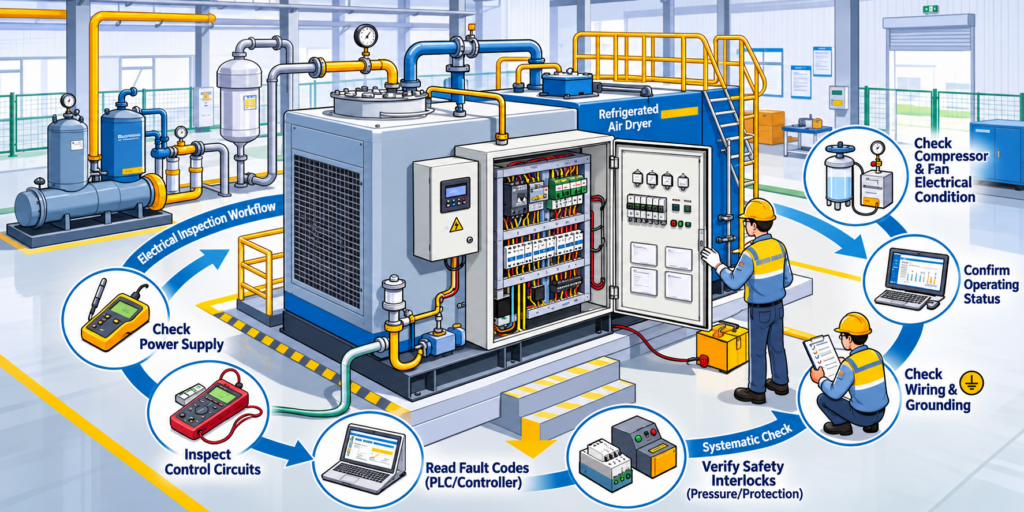
A structured refrigerated air dryer electrical inspection should cover five critical areas: power supply, control circuits, compressor and fan electrical components, safety interlocks, and wiring integrity.
This guide explains what maintenance teams should examine during scheduled preventive inspections, which warning signs deserve attention, and how to organize the inspection process safely.
For a separate guide focused specifically on dryers that have already stopped starting, see Refrigerated Air Dryer Not Starting: Causes and Troubleshooting.
1. Start With Electrical Safety and Equipment Documentation
Electrical inspection should begin with the correct documentation and a clear understanding of the equipment configuration.
Not every refrigerated air dryer uses the same control architecture.
Smaller units may use single-phase compressors, starting capacitors, and relatively simple controllers. Larger industrial dryers may use three-phase power supplies, contactors, motor protection devices, phase monitoring relays, and PLC-based control systems.
Before inspection, maintenance personnel should identify:
The equipment model and serial number.
Rated supply voltage, frequency, and phase arrangement.
Electrical wiring diagram and terminal identification.
Compressor and cooling fan specifications.
Controller alarm descriptions.
Required safety interlocks and restart conditions.
Manufacturer-recommended inspection procedures.
Essential electrical safety precautions
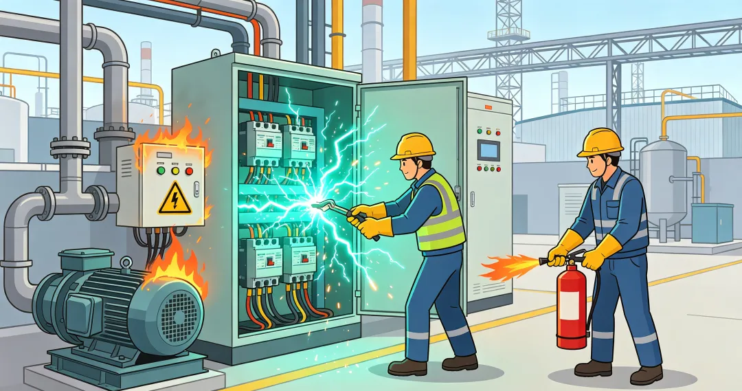
Electrical inspection and testing must be performed only by appropriately qualified personnel.
Before opening an electrical enclosure or carrying out de-energized testing, follow the facility’s approved isolation and lockout/tagout procedures.
This includes identifying all relevant energy sources, isolating them, preventing unexpected re-energization, and verifying the absence of voltage using an appropriately rated test instrument.
Stored electrical energy, including energy retained in capacitors, must also be addressed using approved procedures.
A refrigerated dryer can contain electrical, pneumatic, mechanical, and refrigeration-related hazards. Isolating the electrical supply alone does not necessarily make every component safe to service.
Voltage measurements on energized circuits, when necessary, require a separate qualified-person electrical safety procedure and appropriate protective measures.
Never bypass protective devices, defeat safety interlocks, or repeatedly restart a unit that continues to trip.
2. Check 1: Power Supply and Electrical Distribution Integrity
The first electrical inspection area is the complete power supply path, from the external distribution system to the internal control power supply.
An unreliable power connection can affect the entire dryer, even when its refrigeration components are mechanically sound.
2.1. External power supply inspection
Confirm that the power distribution system matches the dryer’s rated electrical requirements.
The inspection should include:
Main disconnect switch and circuit breaker condition.
Emergency stop status, where installed.
Incoming cable condition and visible insulation damage.
Terminal tightness according to the manufacturer’s specified procedures.
Signs of discoloration, overheating, corrosion, or burned connections.
Appropriate labeling of disconnect devices and conductors.
Loose or deteriorated terminals can increase resistance and generate localized heat.
Repeated breaker trips or damaged connections should be investigated rather than treated as routine operating events.
2.2. Incoming voltage and phase condition
For three-phase equipment, qualified personnel may need to verify the supply voltage, phase availability, voltage balance, and phase sequence using approved diagnostic procedures.
A phase imbalance or missing phase can increase motor stress or activate an electrical protection relay.
However, voltage measurements require the correct electrical safety conditions.
With power isolated, personnel verify the absence of voltage. Measuring actual incoming supply voltage requires an authorized energized test procedure.
Acceptable voltage and phase conditions must be determined from the equipment nameplate and manufacturer’s specifications rather than assumed to be identical for all dryers.
2.3. Internal control power supply
The control system may use a transformer, switching power supply, protective fuses, or dedicated control circuit breakers.
During an appropriate de-energized inspection, check:
Fuse and fuse-holder condition.
Control transformer or power supply condition.
Terminal integrity.
Wiring insulation.
Signs of overheating on circuit boards or connectors.
Evidence of moisture entering the electrical cabinet.
If control power is suspected to be abnormal, its electrical measurements should be performed by qualified personnel following the relevant test procedure.
A blown fuse should never be replaced with a higher-rated component unless specifically authorized by the equipment manufacturer.
The cause of the original fuse operation must be identified.
3. Check 2: Contactors, Relays, and Control Logic
After checking the power supply path, the next area is the control system.
The controller determines when the compressor, cooling fan, valves, and protective circuits are permitted to operate.
A fault in this area may create intermittent problems even when the electrical supply itself is normal.
3.1. Contactors and switching components
Contactors are used in many industrial refrigerated dryers to switch compressor or fan motor circuits.
During a safe de-energized inspection, examine:
Contact surfaces for excessive wear or burning.
Coil and terminal condition.
Mechanical damage.
Signs of overheating.
Loose connectors.
Contactors that have been sticking or operating inconsistently.
Where appropriate, a qualified technician may compare coil resistance with the manufacturer’s specified values.
The coil resistance alone does not establish that a contactor is functioning correctly. Mechanical operation and contact condition must also be considered.
3.2. Overload relays and motor protection
Thermal overload relays and other motor protection devices are intended to interrupt operation under specified abnormal conditions.
If an overload device has operated, the inspection should establish why.
Potential causes can include:
Excessive motor current.
Supply voltage problems.
Cooling fan failure.
Motor electrical faults.
Excessive thermal load.
Mechanical or refrigeration-related problems.
A protection trip is a diagnostic symptom, not merely a reset requirement.
Do not reset an overload relay repeatedly without investigating the cause of the trip.
3.3. Temperature controllers, timers, and PLCs
Depending on the dryer design, the control system may include:
Temperature controllers.
Time-delay relays.
Electronic control modules.
PLCs.
Pressure or temperature sensors.
Alarm and communication interfaces.
Inspect accessible wiring and connectors for damage, looseness, or signs of overheating.
For PLC-controlled equipment, record the alarm code, fault history, and operating state before clearing alarms.
This information may be essential for identifying intermittent failures.
Controller configuration changes should only be made by authorized personnel using the correct equipment parameters.
3.4. Phase protection and compressor restart delay
Some three-phase dryers use phase protection relays that inhibit operation when a phase is lost, the phase sequence is incorrect, or the supply condition is outside the permitted range.
If the control circuit is locked out, verify whether the phase protection device has detected an actual supply problem.
In addition, many refrigeration compressors use an anti-short-cycle timer.
This timer prevents immediate restart after a shutdown to protect the compressor and associated electrical components.
A compressor that does not start immediately may therefore be responding normally to a programmed delay.
Confirm the specified restart delay before interpreting the condition as an electrical fault.
4. Check 3: Refrigeration Compressor and Cooling Fan Electrical Components
The refrigeration compressor and condenser fan are major electrical loads in many refrigerated air dryers.
Their electrical condition can directly affect cooling performance, operating stability, and protective shutdown frequency.
4.1. Compressor electrical inspection
The compressor inspection should focus on its electrical supply, motor protection, terminal connections, and starting components where applicable.
Qualified maintenance personnel may evaluate:
Compressor terminal condition.
Visible evidence of overheating.
Motor winding resistance.
Insulation condition, where manufacturer-approved testing is appropriate.
Starting components on applicable single-phase designs.
Protective device condition.
Abnormal electrical fault history.
For three-phase motors, winding resistance readings can help identify certain open-circuit or severe imbalance conditions.
However, the acceptable resistance relationship depends on the compressor design, measurement method, winding temperature, and manufacturer data.
A universal rule that all compressor winding resistance values must differ by less than 5% should not replace manufacturer specifications.
Furthermore, a basic DC resistance measurement cannot reliably identify every inter-turn winding fault.
If winding or insulation damage is suspected, further diagnosis should follow the compressor manufacturer’s approved procedures.
4.2. Starting and running capacitors
Some single-phase compressor designs use starting or running capacitors.
Possible warning signs include:
Swelling or deformation.
Leakage.
Heat damage.
Electrical connection deterioration.
Capacitance values outside the specified range.
Capacitor inspection and testing must be carried out by qualified personnel using proper isolation and stored-energy discharge procedures.
Not every compressor uses an external starting capacitor, so this inspection is configuration-dependent.
4.3. Condenser cooling fan electrical inspection
The cooling fan helps remove heat from the refrigeration condenser.
If the fan motor or its electrical circuit fails, condenser temperature and refrigeration pressure may rise.
Electrical inspection may include:
Fan motor terminals and connections.
Winding condition.
Capacitor condition, where applicable.
Fan contactor or relay condition.
Signs of damaged wiring.
Motor protection indications.
Mechanical fan obstruction and bearing condition should also be considered when investigating excessive motor current or protection trips.
For water-cooled refrigerated dryers, the cooling arrangement differs, so fan-related checks may not apply.
For broader equipment servicing beyond electrical inspection, consult Lingyu’s refrigerated air dryer maintenance guide.
5. Check 4: Safety Protection Devices and Interlock Signals
A refrigerated air dryer may stop or refuse operation because a protection device has detected an unsafe or abnormal condition.
These devices are not optional obstacles to restarting the machine. They form part of the equipment’s protection system.
5.1. High-pressure and low-pressure protection
Many refrigerated dryers include refrigerant pressure protection devices.
High-pressure protection may operate when the refrigeration circuit cannot reject heat effectively.
Possible contributing factors include:
Dirty condenser surfaces.
Inadequate ventilation.
Cooling fan malfunction.
Insufficient cooling-water flow on water-cooled models.
Other refrigeration circuit abnormalities.
Low-pressure protection may operate under different conditions involving refrigerant pressure, temperature, flow, or refrigeration component performance.
An electrical alarm alone does not establish the precise refrigeration fault.
Pressure switches, sensors, and the refrigeration circuit must be evaluated according to the manufacturer’s diagnostic instructions.
Never bypass a pressure protection device to force the compressor to operate.
5.2. External interlocks and operating permissions
Some industrial installations coordinate the dryer with the compressor, remote control system, plant monitoring network, or other auxiliary equipment.
Possible control signals include:
Remote start/stop permission.
Compressor running status.
Equipment fault feedback.
External emergency stop.
Cooling system permissives.
Condensate drain or liquid-level alarms, where installed.
An interrupted interlock or missing operating permission can prevent the dryer from starting even when its internal components remain functional.
The inspection should compare the expected control state with the wiring diagram and system control logic.
5.3. Confirm protection status before reset
When a protection or interlock alarm is recorded:
Identify the device and record its fault indication.
Determine whether it responded to a genuine abnormal condition.
Correct the underlying cause using the approved service procedure.
Restore operation only after the required safety checks have been completed.
Resetting a protective device without resolving its cause can result in repeated shutdowns and additional equipment damage.
6. Check 5: Wiring, Insulation, and Protective Grounding
Electrical wiring connects the power supply, controller, sensors, motors, and protective devices.
Although wiring problems may appear minor, poor connections and insulation damage can produce intermittent faults that are difficult to reproduce.
6.1. Wiring continuity and terminal condition
During a properly isolated inspection, pay particular attention to:
Terminal blocks.
Plug connectors.
Cable entry points.
Areas exposed to vibration.
Wiring near hot components.
Locations where cables may rub against metal edges.
Signs of moisture or contamination inside enclosures.
A loose terminal may create intermittent control problems or excessive heating.
Damaged insulation may contribute to short circuits or earth faults.
Continuity testing should only be performed on safely isolated circuits in accordance with the wiring diagram.
6.2. Insulation resistance
Insulation resistance testing may help identify deterioration in appropriate motor or wiring circuits.
However, electronic controllers, sensors, variable-frequency drives, and other sensitive equipment can be damaged by incorrect insulation testing.
Before testing, technicians must determine which components need to be disconnected or otherwise protected, following the equipment manufacturer’s instructions.
Test voltage and acceptance criteria must be appropriate for the circuit being assessed.
6.3. Protective grounding
Inspect protective earthing connections for:
Loose or corroded terminals.
Damaged protective conductors.
Improperly modified connections.
Missing bonding conductors.
Signs of overheating or mechanical damage.
Protective grounding and bonding help provide a safer fault-current path when properly installed.
Electrical verification must follow the applicable electrical installation requirements and qualified-person procedures.
7. Refrigerated Air Dryer Electrical Inspection Checklist
The following checklist summarizes the five core inspection areas.
| Inspection area | Key items | Warning signs |
|---|---|---|
| Power supply | Disconnects, breakers, fuses, cable terminals, rated supply | Repeated trips, overheated terminals, unstable supply |
| Control circuits | Contactors, relays, timers, controllers, PLC alarms | Burned contacts, control faults, unexplained delays |
| Compressor and fan | Motor connections, protective devices, approved electrical tests | Overheating, abnormal current, repeated motor trips |
| Safety and interlocks | Pressure switches, overloads, external permissives | Persistent alarms, missing permissions, repeated lockouts |
| Wiring and grounding | Insulation, continuity, terminals, protective earth | Loose connections, damaged cables, insulation faults |
The actual checklist should be adapted to the dryer’s electrical drawing and installed components.
Not every dryer includes all the devices listed above.
Suggested preventive inspection routine
Rather than waiting for a major shutdown, maintenance teams can incorporate electrical condition checks into their existing preventive maintenance program.
During routine operator checks:
Review controller alarms and operating status.
Note abnormal shutdowns or repeated restart delays.
Observe unusual fan or compressor operating behavior.
Check externally visible indicators without opening energized electrical enclosures.
During scheduled qualified maintenance:
Inspect connections and electrical component condition after safe isolation.
Review contactor and protection-device history.
Check relevant motor and control components using approved methods.
Verify interlock documentation and alarm records.
Record findings and corrective actions.
Inspection intervals should be determined by the manufacturer, equipment duty cycle, environmental conditions, and the facility’s maintenance program.
Electrical panels exposed to vibration, dust, heat, or moisture may require closer monitoring.
8. Common Mistakes to Avoid During Electrical Inspection
Mistake 1: Replacing the Compressor Before Checking the Control Circuit
A compressor that is not running may be receiving a valid stop command from a protection or control device.
Better approach: Review the controller state, alarm history, supply conditions, and protective devices before concluding that the compressor itself has failed.
Mistake 2: Repeatedly Resetting Protection Trips
Repeated resets can hide the original fault and expose equipment to further damage.
Better approach: Record the trip, determine its cause, and complete the required corrective action before restarting.
Mistake 3: Applying the Same Electrical Test Limits to Every Model
Acceptable motor resistance, insulation conditions, voltage tolerances, and control sequences vary by equipment.
Better approach: Use the dryer’s wiring diagram and manufacturer-approved test criteria.
Mistake 4: Confusing Normal Restart Delay With Equipment Failure
An anti-short-cycle timer may intentionally prevent immediate compressor restart.
Better approach: Check the programmed delay and operating conditions before starting fault diagnosis.
Mistake 5: Performing Electrical Measurements Without Proper Isolation
Electrical shock, arc-flash hazards, and unexpected equipment movement can occur when electrical maintenance is not appropriately controlled.
Better approach: Use qualified personnel, approved isolation procedures, suitable test equipment, and the manufacturer’s service instructions.
For wider operating risk management, see Lingyu’s compressed air system safety guide.
Conclusion: Inspect the Electrical System Before Minor Problems Become Major Shutdowns
The electrical system of a refrigerated air dryer operates as an interconnected network of power distribution, controls, motors, protective devices, and wiring.
A reliable inspection process should follow a consistent order:
Power supply → Control circuits → Compressor and fan circuits → Protection and interlocks → Wiring and grounding
This sequence helps maintenance personnel organize their checks, identify developing faults, and avoid unnecessary component replacement.
More importantly, preventive electrical inspection supports stable dryer operation, reliable compressed air treatment, and reduced unplanned downtime.
The goal is not simply to restore power after a failure, but to identify deteriorating electrical conditions before they interrupt production.
Need Technical Support for Your Refrigerated Air Dryer?
Lingyu provides industrial refrigerated air dryer solutions for a range of compressed air capacities and operating conditions.
If your dryer experiences repeated electrical alarms, unstable operation, or protective shutdowns, our team can help review equipment specifications and discuss suitable maintenance or replacement options.